
UPDATE – follow our new Smart Home build here – Automated Home 2.0
Welcome to the Automated Home Wiring Guide. This guide documents the installation of the various wiring systems around our new “automated” home. Hopefully the information will be helpful to others faced with the same task, or provide inspiration to those considering it. I’m a firm believer that a picture can paint a thousand words so wherever possible I have included photographs. I hope you enjoy reading this and I’d love to hear from you if you have any comments or suggests.
No products found.
1. Planning
2.What should I cable for?
- Data
- Telephones
- Infrared
- Lighting
- Security & CCTV
- Television / Satellite
- AV Systems & Whole House Audio
- Low Voltage Control
- Heating
3. Cabling Tips & Techniques
4.Other Stuff
5.Resources

Planning
It took a marathon eleven years from the day we decided to build our own home until the day we actually moved in. I won’t bore you with the details but suffice to say that if I never see another planning official in my life it will still be too soon! On the positive side we had lots of time to think about what we wanted in our new house.
The first thing I would advise anyone to do who is thinking of building a house wired for automation is get out a pen and paper (or sit down in front of your word processor) and start to record your ideas. Read the “What Should I Cable For?” section for some examples of the kind of things you might want to include in your system. One thing’s for sure, the more planning you do before you start, the better your system will be.
The second thing I would advise is to start and buy some Home Automation equipment before you finish planning your system. I played with X10 a lot in my old house and this gave me a very good idea of what it could (and could not) do.
The third thing to think about is the future. This will probably be your only chance to include lots of cable in your walls so take advantage of it. Cable is cheap in the grand scheme of things so better to flood wire your house for every perceivable eventuality in the future. You don’t want to be tracking your lovely plastered walls in six months time because you forgot to put a data point beside your bed or whatever.
My research started in 1996 (mostly on American websites and the comp.home.automation newsgroup). It gave me a good starting point and distilling the information down the advice in a nutshell was to put a minimum of 2 CAT5s and 2 TV Coax to every room in the house. My house does have as few as two CAT5 cables to some rooms while others (like the AV Room) have as many as 15. The advice also states that all cables should be “home run” back to a single location known as “Node Zero”. See the Node Zero section for more information.
Obviously the planning stage will be very different if you are designing a system to retrofit into an existing home rather than a new build. As our project was the latter I cannot advise on the finer details of retro fit but hopefully there will still be lots of information and ideas in this article that are relevant. Also make sure to read Nigel Orr’s “Retro Wiring Guide“.
When we were building you’d have been lucky to find an Architect in the UK who had experience in designing a house with automation in mind, however that’s changing now. Many are now open to the idea of incorporating new technology into your home. If you plan to cable your own home rather than use a smart home installer then it’s also important to employ an open-minded electrician. Although mine had never heard of X10 or home automation he was interested to see the outcome. Indeed at the end of the project I had to get him some X10 modules so he could “have a play with them” in his own house…another convert?

Data
No modern home should be without a LAN (local area network). Think of where you might plug in a PC. In the study certainly, probably the kids bedrooms too. Don’t forget laptops. Even if you don’t have one now think of the future. You may envisage sitting with your laptop on your knees in the lounge, or Imagine sitting in bed typing up a report and sending it to the printer in the study before switching the light off and going to sleep. Think of where you might like a touch screen in the future. In the Kitchen for example. Remember things like print servers as well. It’s clear that even if you only have a couple of PCs at the moment there is a need for many LAN sockets around the rooms in your home, never mind all the future devices that may have LAN ports.

Wi-Fi is now so inexpensive you can easily add wireless network access to your laptop, tablet etc anywhere in the house. Without getting too deep into the great wired vs wireless debate however, the advantages of wired LAN points are still reliability, speed, cost and security. Wireless devices continue to become faster and even cheaper, but ultimately the more successful it becomes the more potential headaches there will be for users, especially in built up areas. We have added a wireless access points so we can use our mobile devices around the home. The wireless setup complements but does not replace the existing wired LAN.
Hubs have become much more affordable in recent times. A simple 4 port 10meg, desktop hub can be picked up for as little as £30. I wanted a rack mountable hub and was able to purchase a dual speed 10/100 16 port one for under £200 (inexpensive 2nd hand 10BaseT hubs are available from many computer fairs as users switch over to the new 100BaseT units) . 16 ports may sound like overkill (I only have 4 PCs and a laptop so far) but this means I can have 16 sockets round the house permanently wired as network points. If you buy a 4 port hub you may find yourself going to the patch panel every time you want to move your laptop from the kitchen to the bedroom etc.
The data cables all terminate in my Node Zero where they are punched down into a patch panel. This allows the various outlets round the house to be changed from say a data point to a phone point within a few seconds.

Rack Mark1
Shortly after moving in it was clear the small rack would not be big enough to cater for the other equipment I wanted in there. I have now upgraded to a 42U rack. This gives me the room to put the patch panels, hub, CCTV Switcher, HomeVision, 3xPCs, UPS etc all together and in some sort of order.

Rack Mark2
CAT5. No, not someone’s fifth feline but a type of cable “Category Five” comes in several varieties. It’s a general purpose LAN cable consisting of 4 pairs (8 cores in total) inside an outer insulating cover. UTP (Unshielded Twisted Pair) is the most common form and what we used for our job (Delta Unshielded Solid Core CAT5 to be exact). Solid core is more prone to breaking with constant movement but for permanent installations like this, solid core is the correct type.
Stranded CAT5 is much more expensive plus it won’t punch down into a patch panel properly. Stranded CAT5 is mainly used for patch leads that get a lot of bending movement. Shielded CAT5 is also available. Again this is much more expensive and not required for most installations. CAT5 support network speeds of up to 1 Gigabit at the time of writing. 100 Megabit hardware (hubs and NICs) can be obtained for much more reasonable costs.
Telephones
Tricky one this. With so many great cordless DECT phones about it would be easy to scrimp on the hardwired phone points. Again, think of the future. You may add a second line or ISDN/Highway. That’s the beauty of your own flood wired home. The 2 CAT5s in the kitchen can change from being one phone point and an unused data point to two phone points in a few minutes should you add an extra line. Remember about fax machines and PBXs too.
We had BT Highway installed. This is a form of ISDN which is more suitable to the home environment. You get a box with for ports. Two analogue and two digital. You get three phone numbers (2 voice and 1 data) and you can have any two lines out of the three in use at any one time. You might have 2 voice calls, or a voice call and a data call or even 2 data calls by binding the two 64bit ISDN channels into one 128bit connection! The roll out of BTs ADSL will shortly give home users access to huge bandwidth and permanent connections to the Net.
You can cut your BT plugs off your phones and crimp on RJ45 plugs instead. Or you can buy RJ45 to BT adapters. That way you still have the option to change a socket from a phone to a data point quickly and easily.


HomeHighway Box RJ45 to BT Phone Adaptors
Infrared
An important but often overlooked part of any home automation system is the Infrared distribution. So many devices are now controlled via IR it is vital to include this in your planning. There are two main ways of sending a dedicated IR signal round the house.

The first is the IR-RF-IR method. IR signals are picked up by a receiver, converted to a radio signal and then transmitted. These radio signals are then picked up by a receiver in the room housing the equipment, converted back into IR and re transmitted. I have used several such devices (such as the X10 Powermids pictured above) and found them to be unreliable at best.
The second (and by far the best) way is to distribute IR via a hardwired network. IR can be sent round the house over existing TV coax. However special bypass kits are required every time the signal passes through distribution amp. With several rooms and several amps you could soon need an awful lot of bypass kits. Once again CAT5 is just right for the job.
Xantech make a huge range of high quality IR distribution gear. While these may be perfect for some, others may be working on a tighter budget. After a long time trying to find an IR receiver that would fit into a standard UK wall box (and something that didn’t cost an absolute fortune) I gave up and decided to ask for Keith Doxey’s help in designing a custom one. I sourced a faceplate and lens assembly that could (with Keith’s expert knowledge) be turned into an IR receiver. The picture shows the first prototype and I’m pretty please with it! The module is easily connected to a CAT5 cable and then routed back to HomeVision (although it would be possible to use the module stand alone as well). Remember some rooms may need IR transmitters as well as receivers.
It would be possible to create an “IR Transceiver” in this wall box. However, again through experience, I would not recommend this. This would entail the use of a “blaster” type IR transmitter that would be expected to control all the equipment in a given room from that wall unit. The best way to control equipment is by using mini-emitters attached to each individual component.
“Xantech” produce a commercial range of IR distribution equipment. Although it is undoubtedly nice gear it can be pretty expensive.

Lighting
After looking at many other systems including Lutron, LiteTouch, KNX / EIB, CEBus and Futronix I finally decided on X10 Din Rail modules for my lighting. As I have said many times before, X10 is far from perfect. However, it is readily available, relatively cheap (prices continue to fall) and best of all easy to interface to. Choosing X10 lighting allows many systems throughout the house to communicate with each other. For example the alarm can control the lights (turning every light in the house on in the event of a burglary or fire for example). HomeVision likewise can control the lights as well as swapping information with the alarm system (such as is the house occupied or is it light or dark). Infrared signals from Pronto and various other remotes can easily be converted to X10 signals via the infrared commander (IR-543 / IR-7423). The DIN Rail modules also have the advantage of “memory dim” allowing the creation of “Scenes”. The newer LD11 Din Rail modules now include soft start (they fade up gradually from zero when switching on, and fade down to zero when switching off). They also support
Scenes are created by combining 1 or more circuits of lighting at preset levels. For example you may have a “Cleaning” scene where all the lights in the room would be on at 100%. You may have a “Movie” scene where table lamps are switched off and ceiling halogens are at 10%. A “Party” scene may have table lamps at 75% and ceiling halogens at 25%. You get the picture.
The picture above shows the Clipsal wall switches I am using with the momentary contact switch modules fitted. This switch has control of 4 circuits
If you decide to use X10 Din Rail modules like I did here is some important advice for your electrician.
- Leave some space between the DIN rail dimmers. Two against one another is OK, but it’s better not to have three together on a rail. At one of its sides, a DIN rail dimmers needs about one centimetre of space in order to avoid side-effects due to heating.
- When wires run too close to one another, some weird behaviour can occur. It seems it does not happen if the length of the wiring is less than about 10 meters. Above that, X-10 recommends separating the wires.
- Where it is impossible to separate the wires, a mains relay at the module may fix the problem.
Unfortunately this information didn’t come to me until after all the wiring was complete, floors down and walls plastered! However, out of 34 circuits I only had two that were effected by this problem. Both were on faceplates that had 4 switches/circuits and separating the wires in the wall box cured the problem.
I decided to install a spare 47mm deep wall box beside every light switch in the house and then run 2 CAT5s to them. In the future should I decide to change over to a low voltage controlled lighting system like LiteTouch or Lutron then the wiring is already there. One CAT5 would probably be enough to each room for this but I’ve run 2 just in case. I may use some of the spare conductors for temperature sensors.
90% of the lights in our home are halogens. However we did not use 12V halogens but the new generation of mains halogens. These look identical to the low voltage version but obviously they don’t require a transformer. It seems to be a common problem with X10 that certain types of transformer (usually the electronic variety) can completely kill the X10 signal round the house. So, in order to avoid any such problems I decided to go with these new mains lights. So far they are performing well. As to bulb life and reliability, well, asking me in a years time!
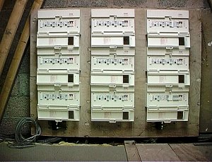
The picture above shows the 9 consumer units housing the 34 DIN Rail modules. I originally intended to put the modules in Node zero but quickly realised they would take up too much room. After a quick re-think I decided to site them against a gable wall in the loft. Once the modules addresses have been set there is very little maintenance apart from replacing fuses. this position is also more central in the house so helped to keep the cable runs shorter for the electrician. Not having all this in node zero also means there is a lot less mains cables in there and therefore less interference. Note the bundle of CAT5s at the bottom left of the board. These have been left for CCTV, CONTROL, NETWORK POINT

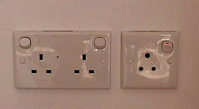
I added some 5amps circuits in some of the rooms for table lamps. These are wired back to a DIN Rail dimmer so they can be controlled remotely. This also gives the advantage of being able to turn on or off several lamps in the room from the wall switch rather than going round and switching them all individually. These 5amp points were all fitted with a round pin wall socket so as to avoid anyone plugging in an appliance and damaging it as the voltage is reduced during dimming.
Security
After much research I had decided on the Napco Gemini alarm panel. Then I stumbled upon a new UK system called Comfort. Comfort is an extremely competent panel and can form the centre of a Home Automation system.
![]() I contracted a local alarm company to do the cabling work for the Comfort Alarm system. They used 8 core screened cable as advised by Comfort. They fitted all the PIR’s and keypads and wired then back to the panel.
I contracted a local alarm company to do the cabling work for the Comfort Alarm system. They used 8 core screened cable as advised by Comfort. They fitted all the PIR’s and keypads and wired then back to the panel.
 Comfort can do many exciting things. For example you can control appliances in your home via phone from anywhere in the world! In place of a doorbell, Comforts door phone makes all the telephones in the house ring. Simply answer the phone to talk to whoever’s at your door. When the house is unoccupied and the alarm is set, Comfort can call our mobile and you can talk to whoever is at your door without them even knowing that you’re not actually inside! If your mobile is off or out of range Comfort will even record a message from your visitor. With it’s inputs and outputs Comfort can interface to things like electric garage doors, wireless transmitters etc etc.
This picture shows the alarm and expansions panels in place and the cables from the various sensors and keypads starting to enter the enclosures ready for connection.


I used Vehicle Alerts from Lets Automate Ltd as my driveway sensors. These detect a change in the electrical field around the probes buried along side the drive. in other words anything large and metallic moving will be detected. The great advantage of this kind of sensor is that it doesn’t pick up “wildlife” moving about, trees swaying etc.
Another great feature of the Vehicle Alert system is that it provides an output for alarms that allows you to wire it straight into Comfort. When a car enters our lane we hear “Far Drive Movement” over the alarm keypads around the house. As a car gets nearer the house we then hear “Near Drive Movement”. With two detectors we are able to tell the direction of travel. Using a HomeVision macro the outside lights are turned on if it is dark and the vehicle is in-bound. HomeVision also writes the date, time and direction (in or out) to a log file.
CCTV
When we were building in the late 1990’s, domestic IP CCTV cameras were still a way off. However, today they are really affordable – check out our CCTV section. The major advantage of IP cameras is the ability to view your home form anywhere in the world on a computer or smartphone via the internet.
Television / Satellite
I ran 2 coaxes to every room except the AV room which has 5 (more on that later). 2 coaxes allow you to have an upstream and downstream cable or perhaps the second cable may be used for a digital satellite tuner in the future. Hedging my bets I also ran 2 CAT5s to every TV point in the house. There are already commercially available systems for distributing audio and video over CAT5. While these are expensive at present they will undoubtedly get cheaper. Keith Doxey is developing his own version of the hardware (christened KAT5), I have seen a demonstration with one of his prototypes and it certainly is impressive! You can send signals for literally hundreds of metres without loss of quality. The advantages of this are clear. Firstly CAT5 is much cheaper than CT100 Coax. Secondly many building are already cabled with CAT5 but have no coax installed and thirdly, CAT5 allows you to send stereo and S Video from your DVD player or VCR to your bedroom! Of course you could use these units to send pictures and sound from other sources like whole house audio systems, CCTV etc.
I didn’t want to spoil the look of the house by mounting aerials or satellite dishes on it. I decided to mount my satellite dishes a few metres away from the house in the back garden and put the aerials in the loft. After a survey we decided to put the dishes even further away from the house in order to give the motorised dish a better view of the Clarke Belt. I asked our builder to concrete in a couple of poles for the dishes. A few days later a huge hole appeared with what looked like the foundations for another building in it!


The satellite platform my builder created. These dishes aren’t going to go anywhere!
A large pole for the 1.2 metre motorised dish and a slightly smaller one for the 80cm dish for Sky analogue and the 45cm dish for Sky Digital. I could have used the 80 cm dish with two LNBs to receive both Sky analogue and Digital but hey…the digital dish was free and 3 dishes looks cooler than 2 right 🙂 The platform is over 60 metres from the house and has 4 CT100s plus the motorised cables running from it underground. All of the cables go straight into the AV room bar one which one goes to Node Zero. I have an old analogue receiver in there which I will use to pipe BBC Radio round the house.
American sites talk a lot about RG6 cable. My friend who owns a satellite and aerial distribution business laughed we I asked him for RG6. Enough said. He recommended CT-100 which is a double screened satellite grade cable. I also asked him about CT-125 but he said this was overkill for a domestic application. While undoubtedly CT-125 has a lower loss, it is thicker so harder to route and terminate. The quality of the pictures from my satellites over 60 metres away from the house bear testament to the fact that CT-100 is as high a grade cable as you should ever need.
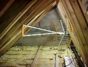
Terrestrial TV pictures come from this Televes aerial installed in the loft. We are lucky enough to be in good line of site with the TV transmitter that serves out are so we get great pictures whist not spoiling the outside of the house with a mast on the chimney.
AV System
The AV system lives in the imaginatively titled “AV Room”. I think I caught the Home Cinema bug back when I first wired up the headphone socket of my black and white portable TV to my Hi-Fi amp. Thankfully things have moved on a tad since then and I have been building my system ever since.

I had decided to cable the AV Room ceiling so that I could add a projector in the future. However, the more I thought about it the more I realised if I didn’t fit the projector when the house was being built I probably never would. I chose a “Seleco 320 Plus” CRT projector and my builder accepted the “challenge” of mounting this 37 kilo monster on the AV Room ceiling.
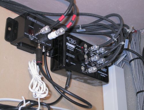
For the run up to the projector mounted on the ceiling I used Delta 75-ohm mini-coax. Each cable contains 4 coaxes and I ran 3 separate cables giving me 12 coaxes in total. This allows me to feed composite, S-video and component signals up to the projector. I also ran two CAT5s from the projector back to node zero. The projector has 2 relay outputs that close when powered on and I make use of this later to set a flag in HomeVision.


The second update was to move to a HiDef system and this required the ceiling to be tracked. We now have a much smaller HD projector attached directly to the ceiling with a bracket.

One of the corners of the AV Room.
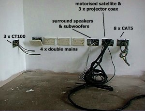
These sockets will be behind the AV system.
The picture above shows the sockets used for the AV system.
Unsurprisingly the first of the 4-gang trailing sockets has been added already!
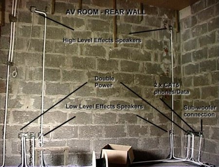
The rear wall of the AV Room.
79 strand in walls of AV room
CT100 for LFE channel in Dolby Digital and DTS 5.1

Whole House Audio
In our opinion, if you are looking for a whole house audio solution these days, you can’t do better than the Sonos system – Read our review here
Back at the time we were building, we looked at several nice whole house audio products like the Linn Knekt and the QED System line. However they were outside of my budget. From memory around £1,500 PER ROOM for the Linn product and even around £3000 for the 4 zone QED box (excluding speakers and installation). So I decided just to run speaker cable to the various rooms with the view to creating a MP3 jukebox in Node Zero at some later stage. While I didn’t want to use “bell wire” at the same time I’m not one of those people who’s into oxygen free, directional, £100 per metre stuff (who is?). So I decided on old faithful – 79 stand.

This picture shows on of the cable runs to a first floor bedroom. The speaker wire has been left in the loft above ready for attaching to ceiling speakers when the time comes (note the colour coded tape on the end to identify the cable).


The 79 Strand and cable clips
79 Strand speaker cable is a good balance between quality and cost. I used it all over the house.
Low Voltage Control
Many HA systems (like HomeVision and the Comfort Alarm) have I/Os and relay outputs to control a multitude of external devices. Things like electric curtains, motorised valves for heating or irrigation, garage doors etc. Again CAT5 is idea for low voltage control.
Heating
We decided to install under-floor heating on the ground floor and conventional radiators upstairs. To my shame the heating is the one aspect of the house that I have yet to automate. The motorised valves used for each zone of the under floor system look interesting. In the future I hope to have HomeVision or Comfort interface with these valves as well as the radiators upstairs and in conduction with the Dallas temperature probes, to automate the heating.

Remember the advise from the Planning section. Always cable for what you need now PLUS what you may conceivably need in the future.
Node Zero
“Node Zero” is the area in the house where all the cables come together. This is described as a “Star” system, where cables are “Home Run” back to a central location. This is different to a “Daisy Chain” system where cables are run from one node to another for example like the phone wiring in most homes.
The more central within the house the location for node zero (for example under the stairs) the less cable you should need to complete the job as the runs will be shorter. However using central areas like this can be less aesthetically pleasing to say the least. For this reason (and having the luxury of designing my system from scratch) I decided to build a small room in the garage to serve as node zero. The extra cable required was a small price to pay for a neat installation. Other popular locations for node zero are in a loft or basement.
|
|
|
|
|
|


Node Zero is built against an exterior wall in the garage. One of the two pipes shown in the photo of the foundations above links into a much smaller 2 inch conduits and runs back to the satellite platform (around 60 metres away from the house). The other pipe runs the complete length of the drive (using 4″ pipe) giving us an easy route should we ever add drive lights, motorised gates etc.
I have installed some of my equipment high up in Node Zero. The things I have put up here out of the way are the alarm system, the vehicle alerts and the BT Highway box.. At present it’s not too easy to work on these items. You need to be standing on the top of a step ladder and the screwdriver you need is never the one up there with you! However, these are items that are pretty much fit and forget, so I shouldn’t have to be up there too often. This leaves me maximum room at “normal” working height below do add more equipment in the future.
Remember to use a cool light source in Node Zero. I have a 2D florescent fitted. It gives a good light and doesn’t get hot when you are working close to it.
|
|
|
|
|
|


Node Zero already contains…
- 19″ rack
- Patch panel
- 10/100 Hub
- Alarm (un-switched spurs)
- Phone / ISDN
- Vehicle Alerts
- HomeVision
- PC
- Electric Sockets x LOTS!
- Generator point
- TV Distribution Amp
In the future I plan to add the following to Node Zero…
- VCR or Digital Video Capture
- MP3 Jukebox
Pulling
Running CAT5 is simple so long as you are careful.
- DON’T pull too hard on the cable
- DON’T kink the cable
- DON’T bend tightly round corners
- Keep a reasonable distance from mains wiring
- Spend a lot of time planning your route BEFORE you start
- Buy several reels to pull multiple cables at once.
- Pull the longest runs first (the bits left on the drum will be long enough for the short runs)
- When pulling cables over cables you have already run use a slow steady pull. Jerking the cable will damage the conductors and cause friction burns to the sheath of existing cables.
- With a steady pull it is easy to detect the cable snagging without causing damage.
- For termination buy the proper IDC tool. It will be 15-20 quid well spent..
- Most important thing of all…..GET A MATE OR TWO TO HELP. Pulling cables by yourself is really hard work and takes 3 or 4 times longer.

The 79 strand speaker wire being pulled in pairs. Those empty CAT5 boxes can be useful!

Keith threading the next run up along the steal beam above the 1st floor ceiling.
 The view above Keith’s head. The 10 foot length of white conduit on the left being used to push a bundle of cables trough the cable and into the next section of the house

Our builder cut a hole in the gable and used a piece of 4 inch pipe to create a neat route for the cables.
This was another one of Keith’s brain waves! He had the idea to use rain guttering as a tray to support the cables in the loft.

This picture shows the cables coming down from the space beside the steel beam. We nailed a couple of strong tie wraps to the roof timbers and clipped the cables to the wood. from there they enter a 3 inch square conduit to travel to the floor.

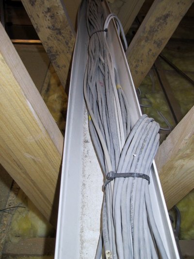
Node Zero is directly beneath this pile of cables.

This is a view from inside Node Zero looking up at some of the cables dropping down from above.
Routing
My good friend Keith Doxey (who runs the excellent DIY Automation website) flew over to spend a week with me cabling the house. On the first morning that Keith and I climbed the ladder up to the first floor our initial task was to workout how we would route the cables from Node Zero to the various rooms around the house.
Strangely I never considered asking my architect to specifically plan into the house a route for the cables. Luckily, after some head scratching, we struck gold! There seemed to be a natural conduit above the first floor ceiling in the form of a steal I-beam.
Although this meant using more cable (as even the wires for the ground floor had to go up above the first floor ceiling before dropping down again into their destination room) the advantages were clear. We wouldn’t have to drill hundreds of holes across the first floor joists saving loads of work and at the same time keeping the data cables well away from the majority of the mains cables already running through those joists.
Labelling / Documenting
OK…Keith and I disagreed on this one. I wanted to use the cable ties with little tabs on them and write a code on each one. Keith wanted to go with his colour coded tape system. In the end though I have to say Keith was right (don’t you just hate a smart ass!) Here’s how Keith describes the system .
“The cable marking system employed uses bands of coloured insulating tape to identify the different cables. It is much quicker than some of the adhesive tapes printed with numbers, and more rugged than writing on the sheath of the cable.
From past experience I have found that even when using a permanent marker the ink still gets rubbed off or becomes illegible due to handling or dirt getting on the cable sheath. An added advantage of using coloured tape is that the cables can be identified from across the room.
The scheme chosen for this installation uses 4 bands of tape using 4 colours. This gives 4x4x4x4 = 256 possible combinations to mark the cables. To increase the capacity of the system either add an extra colour or another band of tape.
- 4 bands of 4 colours gives 256 combinations
- 4 bands of 5 colours gives 625 combinations
- 5 bands of 4 colours gives 1024 combinations
- 5 bands of 5 colours gives 3125 combinations
Colour Sequence is reading towards the cut end of the cable e.g. RRRY is RED RED RED YELLOW with the Yellow band nearest the end of the cable.”
Finally, photograph or video every aspect of your installation. Hopefully you’ll never need this, but if you do, it will be an invaluable reference!
Tools
No specialist tools are required for cabling and pretty much anyone who can hammer a nail into a piece of wood should be competent to cable. You’ll need the following.
- Hammer
- Clips
- Snips
- Step ladders
- Coloured Insulating Tape
- Pole
- Cordless drill
- IDC Punch Down Tool

Additional Considerations
Other Sockets – Remember to get your electrician to leave you a couple of sockets in the loft. You may want to plug in an X10 transmitter like a mini-controller for testing or maybe a laptop or a server up there.

I have a waterproof double socket installed on the outside of one of the gable walls of the house. This is wired back to an X10 appliance module with the view to using it for Christmas Tree lights etc in the future. It will be easy to program the timed operation of anything plugged into this socket in the future by a HomeVision macro. It can also be switched manually from inside the house

- MCBs – Mini Circuit Breakers
- RCDs – Residual Current Devices
 Exterior view of the garage doors
Interior view of the garage doors
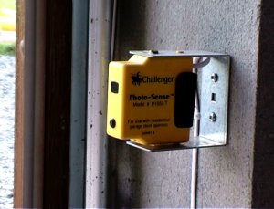
IR “eye” sensors. If beam is broken doors reverse

Visonic 4 channel remote
These are automated with Challenger motors. The supplied wireless remotes have a short range of around 20 metres. This meant that the door wouldn’t be fully open by the time we arrived at it while driving down the lane. So I have now wired in my garage doors to the Comfort Alarm system and can open and close them via a Visonic wireless remote. This increases the effect range to over 300 metres.
Having the garage doors control connected to the Comfort alarm also means I can open and close the doors from using a phone from anywhere in the world. I can also control them over the Web using Comforts new CWI software!
With the possibility of children playing around the garage doors we decided to install the optional IR sensors on the doors. If the doors are closing and the beam is broken the doors reverse immediately. The doors will reverse automatically as standard but only after they have actually hit something!

We fitted a “DriMaster” unit in the loft. This gently blows air through the house via a vent in the ceiling of the hall . This positive air pressure negates the need for vents in window frames and fans in wets rooms around the home. I particularly didn’t want these noisy fans in our bathrooms and en-suite and building control confirmed that with the DriMaster we did not need to fit them.
Water
If you are planning a water feature (fountain, waterfall etc) remember you can automate that too. Irrigation is a less likely requirement in the UK, but an ideal automation project in many other parts of the world. There are plenty of sensors to detect water ingress too, perhaps you have a basement that’s susceptible to flooding?
Time
Keith and I worked on site from Monday to Saturday and got around 95% of the work completed. We had help from another friend for the first two days and of course a very helpful and co-operative builder on-site to make holes in walls etc.
With some good preparation and help from one or two friends it should be possible to get most jobs finished in a week to ten days. If you’re involved in a new build it is worth checking with your potential builders that they have no objections to you doing your own cabling. With a retro-fit time will probably be much longer. However if you are already living in the property you can do it at your leisure.
Costs
In the end we used 2.5 kilometres of CAT5, 400m speaker cable, 500m CT-100 Coax and 1 kilometre of alarm cable. Apart from the cable costs the main expense was the security system and the X10 DIN Rail modules. We also paid more for our Clipsal sockets and switches as well as the extra work required by the electrician to run all the switch cables back to the X10 modules in the loft.
Resources
Automated Home Website
If you’re reading the downloadable version of this guide, then here’s my website
https://automatedhome.co.uk
Automated Home Forums
Attached to the website are the Forums *the* place to get an answer on any HA or related topic.
https://automatedhome.co.uk/vbulletin
UKHA_D Mailing List
The UK Home Automation Discussion mailing list.
http://groups.yahoo.com/group/ukha_d/
Krazy Keith’s DIY Home Automation
An invaluable source of information from the UK’s home automation technical Guru.
Keith is now selling his KAT5 units for sending Audio and Video over CAT5!
http://www.diyha.co.uk
Lets Automate
A great place to buy all your cable and other home automation equipment on-line.
http://www.letsautomate.com
Laser
A great place to buy all your cable and other home automation equipment on-line.
http://www.laser.com
Clipsal UK
Clipsal sell a great range of modular faceplates into which you can snap all sorts
of connectors, RJ-45, TV Coax, Phones, F-Type etc. Used all over our house
and highly recommended!
http://www.clipsal.co.uk
UK’s “Do It Yourself” FAQs.http://www.diyfaq.org.uk
Includes very informative sections on mains consumer units and home security
The UK Newsgroup uk.tech.home-automation
Created in 2002, finally the UK has its own HA Newsgroup
The US Newsgroup
comp.home.automation
The place I discovered Home Automation
Thanks
A special thanks to all those without whom it would not have been possible.
Keith Doxey : James Hoye : Derek Clydesdale : Andrew Roberts
Version 1.07 (Last updated January 2020)
Last update on 2024-04-08 / Affiliate links / Images from Amazon Product Advertising API
your article is a nice one.
thank you for your nice Wiring Guide
Hi, which dish is for 2-way broadband? Is it the large dish? Good idea about putting them far away from the house.
Hi thanks for the very informative guide- can you help advise would you still advise runing 2 off coax to every room? You say in your article CAT5 is much cheaper than CT100 coax – is CT100 coax the grade you would run 2 off into each room?
Thanks Mark. Not sure if CT100 is still available these days. Best to go for the new foam filled COAX now. Try searching for ‘WF100’
Hi ive just finished flood wiring my house and the insulation and plaster board is now to be installed- however i haven’t allowed anything for interconnecting cables like scart/hdmi/optical cables/ audio leads between tvs/dvd/ps3/cinema systems etc?.
I have taken your advice and ran 2 coax + 2 cat5 to each tv point back to my node zero but i havent quite figured out whats going where?? Obviously tv’s in the room but what about the source i.e sky or bluray/dvd player? Would these be in node zero or in the room with the tv? This is all quite confusing but im sure ill get there in the end??? Your help would be appreciated in identifying what other cables if any should i be installing behind the plaster board?
Thanks in advance
Mark
Hi Mark – rather than increase the size of this page, I’ve started a thread on the forums…
https://automatedhome.co.uk/vbulletin/showthread.php?t=2544
Can we use that for comments / questions on the wiring guide from now please.
Thanks
M.
We are just starting a build all systems will be computer controlled, incorporating individual room climate control, HD and networked in every room, fully integrated CCTV and alarm system in and out
This will also include mood lighting systems for the external areas pool patio etc.
We have taken great interest in your article and it has inspired us to go all the way so I blame you for having no money now!!
And living on site in a caravan.
I think that you should maintain this information as long as possible, possibly even posting any retro views now that you’ve lived in. The information presented here is timeless.
Thanks trinifox.
Hi,what a brilliant site,ive been looking for one like this for ages,well explained and documented,as an old sparks,(45),whos let technology pass him by,at great speed,i found it a great update for my skills and am now ready to strip my place and H A the whole lot,so youll be hearing regularly from me pretty soon,once again,Cheers!!!
Hi, excellent case studies and very good photos to convey some complex information. Thanks for sharing
Great system. How hard did you find the intergration with other systems?
I really enjoyed you’re project ! It has now inspired me to do the same I am currently working away ( Instrumentation Eng ) when I return I am going to begin planning my own project ! It is great I have found someone like me in the UK ! Well done I love your house
Thanks for all the info.I am also an old hand at electrics (36 years) and always avoided this ‘new stuff’. I’ve worked with Lutron and wondered if all mains supplies for lights, motors all terminated in your node zero.Any photos available to enhance your already informative site. Well done.
Very interesting article – pity I didn’t see it a couple of years ago!
Living in VietNam, where our basic building material is concrete and Rebar. Planning, followed by yet more planning is essential.
I am a Canadian licenced electrician and have also installed the somewhat antiquated UK Ring Main.
Three types of building have resulted from my labours: a home, two hotels and an office.
All wiring has been distributed through 2-3inch square-profile conduit with separate conduits for different voltages.
Since maintenance and modification is key, great consideration has been given to it.
All rooms/areas are treated as exclusive modules with hallways/corridors providing the backbone services.
Each cable function (power, lighting, communication) is terminated in large (9″ x 9″) junction boxes immediately adjacent to the inside of the room door.
Three square conduits extend from these boxes running along each wall and at very precise heights and spacing.
The power breakers are there (stop people horsing around with other guests rooms) with daisy-chain wiring to each socket pair (one Euro 2-pin and one N. American 2-pin) which are spaced apart 1.2 metres in living areas and every two metres in bedrooms.
The outlets (sockets) are arranged so that every corner, where practicable, has an outlet.
Communication outlets appear adjacent to power outlets and are, as installed, CAT 5, 2-pair telephone and Co-axial.
We only use LED’s at 12 volt for lighting.
In hallways and corridors we have PIR (Passive Infra-Red) detectors which act as motion detectors for security as well as LED ceiling strip lighting. The strip lighting is divided in sectors so as a person moves one strip turns on and another turns off.
If a Fire Alarm occurs, the strips light up sequentially indicating the direction to the nearest exit.
Inter-floor cabling is, naturally, square-profile conduit with access panels at the floor and ceiling on each floor. IT IS IMPORTANT TO STUFF THESE FULL OF FIBRE GLASS WHERE THEY PASS THROUGH THE FLOOR FOR SAFETY PURPOSES.
Each floor has a large, locked, power breaker panel from where each room/area is fed from.
These floor breaker panels all terminate in another breaker panel adjacent to the external power feed.
NOTE: Due to risk of flooding our main breaker panel is situated on the first floor above ground level.
We have batteries on each floor for LED lighting power.
Security wiring provides for an conduit box adjacent to each window and door and is basically a 2-pair telephone cable and a CAT5 (camera/door open sensor).
Kitchen area wiring are outlets in 2-double adjacent outlets (4 total) placed according to likely use.
In closing, I would point out that 99.999% of housing and many offices have but a SINGLE BREAKER, in the main supply feed, and NONE for internal circuits!
Great article! What are the main changes you’d make if you were doing this now (in 2014)? E.g. would you have fewer CAT5 cables because of cheaper and faster WiFi?
Fantastic. I’m wondering the same as Chris. What would you do if you were starting again now?
I am planning to put in some Home Automation on lights and heating. At the moment I am looking at LighwaveRF for the lights, and something z-wave for heating. I want to keep the cost and hassle low, so minimum wiring.
I’m looking for advice as don’t really know what’s best.
Hi Mike – we’ve updated the wiring guide when we’ve changed or added something – or when we feel we should have done something differently (checkout the grey UPDATE panels inline above).
Also take a look at all the systems our Home Automation Systems and Technology Choices page.
Thanks
M.
help please , sooo confused after reading this site time and time again , just fills me with more questions about actual cabling of system.
Is everything back to node zero ?
every coax , cat5 , cctv and alarm cable back to 1 central point.
Also have independant mains feed from consumer unit to each light switch with an additional cat5 , is that necessary?
do all coaxs go to node zero or do you also have coaxs between tv points and loft ( for aerial )?
have wired 5 x coax to loft from node zero , 3 x coax from each tv point to loft , 3 x coax from each tv point to node zero is this necessary .
speaker cable from node zero looped between pairs of speakers each with a cat 5 back to node zero.
speaker cable from each tv point to same speaker locations.
speaker cable from each tv point to node zero.
3 x cat5e from each tv point to node zero.
all cctv and alarm cables back to node zero.
additional 6mm , 2 x 2.5mm and 2 x 3 core power cables to loft.
Have i missed something or am i over wiring for future proofing.
Please help as plastering due to take place in 2 weeks and would like to get it all correct.
regards
wayne soppitt
I installed LSZH 1200MHz CAT7 rather than your CAT5. HDMI over structured wiring requires a minimum of CAT6.
I also installed a 2.4GHz leaky feeder with 802.11b,g&n access point for exelent WiFi coverage.
Thanks for the informative information sharing data…