Wouldn’t it be nice to be able to just glance at your doors and tell if they were locked or unlocked. This Automated Home reader has done just that and can tell the status of each door from the colour of the LED. Read on for the photos and the circuit details…
Submission by Martin Howell Why do it? – When I built my new house, I used the euro style door locks in preference to the more normal Yale type. These locks require you to either turn a key (from the outside) or a knob (inside) to lock the door, they don’t slam lock like a Yale and can’t lock you out if the door blows shut while you are outside.
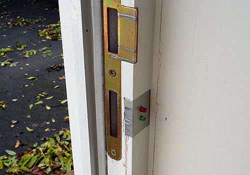
They work great, but its impossible to tell if the door is locked or not without trying the knob. When locking the house it is therefore necessary to physically check each door, a bit of a pain especially when all the lights are out. The garage is attached to the house and has a remote-controlled door, and again the only way to check if the door is locked is to go and look. I needed a way to easily see if the doors were locked, so I ended up fitting a set of LED lights to each door. Using the simple Red = bad, Green = good logic, I fitted a pair of LEDs into the door frame operated by a micro-switch hidden in the lock plate.
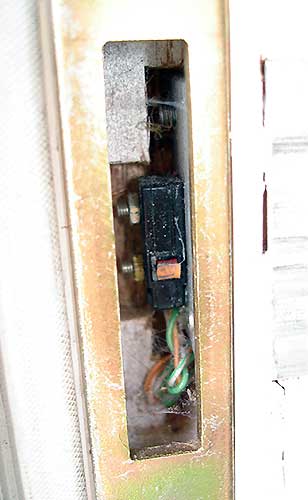
How did I do it? – The switch is a standard micro switch, mounted on to an aluminium plate which is screwed to the inside of the opening in the door frame where the lock tongue goes in. The plate has slots to allow the switch to be adjusted back and forth so that it engages properly with the lock tongue – too close and the tongue fouls on the switch and the door won’t lock – too far away and the switch fails to operate. The wooden doors and frame expand and contract with the weather, and the lock mechanism is not very precise, so trial and error is the only way to get the adjustment right. I fitted a small piece of thin rubber over the switch operating button with super glue to cushion the switch a bit.

The switches have to be the type that have three connections, common (COM), normally open (NO) and normally closed (NC) and a single plastic button that operates it. Mine came from one of the many photocopiers and printers that I’ve cannibalized for parts over the years. There are all sorts of lever attachments for these switches which would make the adjustment less critical, but there isn’t room inside the hole
The lights are fed from CAT5 which carries power from a central 12v power supply located in the ‘engine room’ where the server and network stuff lives. Although CAT5 has 8 wires, I only used 4 of them and stripped away the spares to save space. I wanted to be able to mimic the lights to some central point, so the connections that operate the LEDs at the door are also carried back to the engine room.
The CAT5 terminates on a wall plate close to the door, then the cable is run behind the skirting to the base of the door frame. I machined a slot in the frame of the door and fed the wires up through that, then glued a strip of wood back into the slot to conceal them. The LEDs are mounted to a small piece of aluminium angle, recessed into the door frame, this also conceals the screws that hold the switch and the hole that the wires come through. The LEDs are standard 5mm types, so I drilled 5 mm holes in the plate and super-glued the LEDs into the holes, then fixed the plate into the frame using a couple of dabs of ‘No More Nails’. There’s very little space in the hole, so it was necessary to chisel out a bit of the frame to fit the switch and make room for the wires.
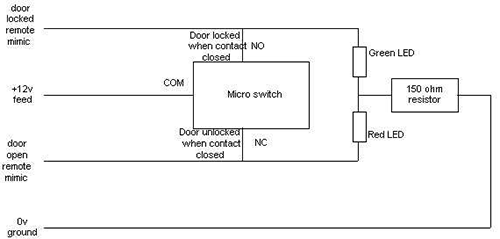
The switches and LEDs are wired as follows:-
- +12v connects to ‘COM’ on the switch
- One leg of the red LED connects to NC
- One leg of the green LED connects to NO
- The remaining legs of both LEDs are connected together, then to a 150 ohm resistor, and then to the 0v wire
- To be able to mimic the lights elsewhere in the house, I also connected wires to the NO and NC connections

The switches will allow for push-on connectors, but thereís not much space so I soldered them all. The LEDs will only work when wired one way round, if they donít light up, just reverse the connections. Because only one LED is live at any one time, only a single resistor is needed. The LEDs can be run from from 5v, but they will be less bright and harder to see in daylight, and I had a spare 12v power supply.
The garage door has a similar arrangement, but because there’s no need to conceal the switch its just mounted on an aluminium bracket screwed to the door frame. The door itself carries another bracket with a rod which engages with the switch, the rod is threaded to allow for adjustment
Other related stuff – The same 12v feed will also supply power to the water detectors mounted under the washing machine and dishwasher, with solenoid valves to shut off the water and sound an audible alarm in the event of a leak (this is still work in progress). I also plan to mimic the status lights on the boiler which lives in the garage inside the house so that I can see if its working properly (more work in progress)

Conclusion – This is one of the most useful and least expensive features in the house, with a very high WAF. When going to bed, just walking through the house I can see instantly if the doors are locked and with all the house lights off the LEDs provide just enough light to navigate around without tripping over things. It was easy to do, cost nothing (already had the parts in my junk box) and works exceptionally well.
No products found.
The next step is to connect the outputs from the door switches into my server where a small application will monitor them and display their status on a web page. The same web page will also display the image from the camera that covers the front door. A spare pocket PC mounted centrally in the house will view the web page over wi-fi. I just need to find a way to interface the ‘mimic’ connections into the PC, any suggestions for this will be gratefully received.
Thanks – Martin Howell
Last update on 2024-04-08 / Affiliate links / Images from Amazon Product Advertising API


This is really cool. When you say easy to do however, running cat5 to every door and device sounds a bit of a pain. For a new build it is brilliant.
To interface to the PC, I would have thought the Arduino thing would help
http://www.arduino.cc/
Martin – could this be done with a single, multi-colour LED?
Hi Martin
Nice work…..If i was going to do something similar i would use a single Bi coloured led..
I think 150 ohm might be a bit low for a standard led connected to 12v dc normally 470 ohm…
Frank
Dave – yes, I had the advantage of a new build which made the CAT5 easy. Didn’t put anywhere near enough of it in, though 🙁
Bi-colour LEDs would be neater, so if I ever did it again, that’s what I would use. The low value resistor gives loads of light from the LEDs (easy to see in daylight, and lights up the room at night!) but will shorten the life of the LEDs, so if/when they blow I will beef the resistor up a bit as Frank suggests
Like it. Shame the circuit doesn’t also feed back door open/closed status to the ‘engine room’ too.
I’ve done something similar, feeding the wires back to an Ocelot that then connects to HomeSeer on my server. I hadn’t thought to put LEDS at the door too.
When I use a touchscreen panel to say we are going out, or going to bed, then HS will check that the doors are locked, if any aren’t, then it uses text to speech through our SONOS system to tell us which door(s) aren’t locked. Connecting up all the windows is work in progress!
The wires are in place to feed status back to the engine room, I’m just trying to find a device that will convert the signal into a USB input that the PC can read. At the moment, this looks like a butchered game pad, and the plan is to write a VB application that will display the results on a web page. This can be viewed on a spare Ameo pocket PC (which has a great touch screen) which will be mounted on the wall in the hall.
The one issue I see with the way you have done this is that you have compromised the already weakest part of the door lock – the framing that the lock extends into to lock the door. I expect it would be very easy to put a shoulder into the door to break in.
Wonder if it can be done with uPVC doors. Just had a look at mine and it would require a bit of surgery to the plastic frame, so would probably invalidate the warranty.
Any way excellent project.
Nice work Martin.
I’m planning on doing something similar using 1-wire technology to monitor all doors, windows and locks. Saves running individual cables to every location and its very cheap.
Cheers
It’s a pity you stripped the cat5, limits futre expansion. A similar system could be done with zigbee, an RF mesh network. All that would be required would be the presention layer, a box with LEDs or adapted to X10 interfaces. I know X10 is wayyyy past its “use by” date.
Nice project, exactly what I want to do for our church. Same problem, many exits and its hard to tell without going to each one if they are locked. Will be a bit of work for me as our doors and frames are all commercial steel building type doors. Will see how it goes. What I am really interested in is the software interface, would be really handy to know status. And even a time stamp possibly to know what door unlocked when. Thanks for sharing this!
Did the same thing but my LEDS are on a switch plate blank I made, so I can check from one spot to make sure all my doors and windows are locked before i goto bed or leave.
Leds only turn on when things are unlocked in my setup.
Problem I have is that without turning the key the latch can be in place but the door can still be opened from outside using the outer handle. Any ideas on how to attack this problem ?
I live in South London , can anyone do this for me or suggest someone who can?